Input Shaper
Input shaping is a technique to reduce or eliminate vibrations (also known as resonance) that occur when the printer moves at high accels. These vibrations can cause visible print defects such as ringing or ghosting, where the surface of the print shows repeating patterns or distortions, especially around corners or sharp changes in direction.
Should be Done Before
- Extruder Calibration must be done.
- Extrusion Multiplier must be done.
- Pressure Advance must be done.
- Temperature Controls must be done.
Required
- DangerKlipper (DK) required for the folowing section(s):
How it Works?
Input shaping works by adjusting the motion commands sent to the printer’s motors, pre-compensating for these vibrations. Essentially, it modifies the acceleration and deceleration profile of the printer’s movements to cancel out the resonance frequencies, allowing higher accelerations without introducing print defects.
Why is it Important?
Input shaping is important in 3D printing because it directly addresses the problem of vibrations or resonance during high-speed movements, leading to significant improvements in print quality and performance. Here are the key reasons why input shaping is crucial:
- Reduces Ringing and Ghosting
- Enables Higher Print Speeds
- Improves Dimensional Accuracy
- Enhances Surface Quality
How to Tune Input Shaper?
Unlike other calibrations, input shaping is more specific to Klipper firmware and requires the installation of certain packages. Below, you’ll find a step-by-step guide on how to set up input shaping for your printer and how to interpret the graphs you generate during the process.
Settings
a) Connect your ADXL345 to your printer.
You can find detailed wiring informations by clicking here.
b) Install the required packages.
SSH into your printer and run the following commands to install packages
- SSH
sudo apt-get update
sudo apt update
sudo apt install python3-numpy python3-matplotlib libatlas-base-dev libopenblas-dev
c) Install NumPy in the Klipper environment by running the command:
- SSH
~/klippy-env/bin/pip install -v numpy
d) Make the required changes to define ADXL345 in printer.cfg.
- printer.cfg
[adxl345]
cs_pin: adxl:gpio1
spi_bus: spi0a
axes_map: x,z,y

[resonance_tester]
accel_chip: adxl345
probe_points:
    # Somewhere slightly above the middle of your print bed
147,154, 20 - caution
You need to include this section if you connected your ADXL345 other than your main controller.
printer.cfg[mcu adxl]
serial: /dev/serial/by-id/<mySerial>
# Change <mySerial> to whatever you found above. For example, usb-Klipper_rp2040_E661640843545B2E-if00
e) Time to run real life tests!
When you type the commands below to console, the specified axis of the printer will start to oscillate. At first, you will be able to see this oscillation, but as the HZ increases, you will only hear the sound. Don’t worry, the sounds are completely normal.
f) Generate the Graphs
After performing the resonance tests, Klipper generates a
.csvfile containing the results of the tests. By running a Python script using the commands below, we can graphically interpret this data by plotting it into a graph.For Axis X Graph
- Console
~/klipper/scripts/calibrate_shaper.py /tmp/resonances_x_*.csv -o /tmp/shaper_calibrate_x.png For Axis Y Graph
- Console
~/klipper/scripts/calibrate_shaper.py /tmp/resonances_y_*.csv -o /tmp/shaper_calibrate_y.pngcautionYou need to delete the older
.csvfiles before you plotting datas to graphs, otherwise script will use both of the.csvfiles to generate the graphs and that'll cause 2 overlapped graphs to each other which makes harder to read and diagnose.
Shaper Models
Klipper offers you 5 different shapers. Each one has its own advantage. You can see few details about them below;
ZV (Zero Vibration): ZV is a basic form of input shaping designed to reduce vibrations by adjusting motor acceleration.
MZV (Modified Zero Vibration): MZV builds upon ZV by offering better vibration reduction, particularly for systems with higher resonance frequencies.
EI (Extra Insensitive): EI input shaping increases the system’s insensitivity to a range of vibration frequencies, allowing for better performance across varied conditions.
2-Hump EI (Two Hump Extra Insensitive): This variant of EI targets two dominant resonant frequencies simultaneously, providing improved performance for systems with dual frequency vibrations.
3-Hump EI (Three Hump Extra Insensitive): Like 2-Hump EI, this input shaping method is designed to target three resonance frequencies.
As written before, each one has their own advantages but we mostly recommend using MZV for our usecase.
Understanding Input Shaper Graphs
In order to understand input shaper graphs generated by klipper, you will need to learn about the basics first. Let's take a look to sample graph below
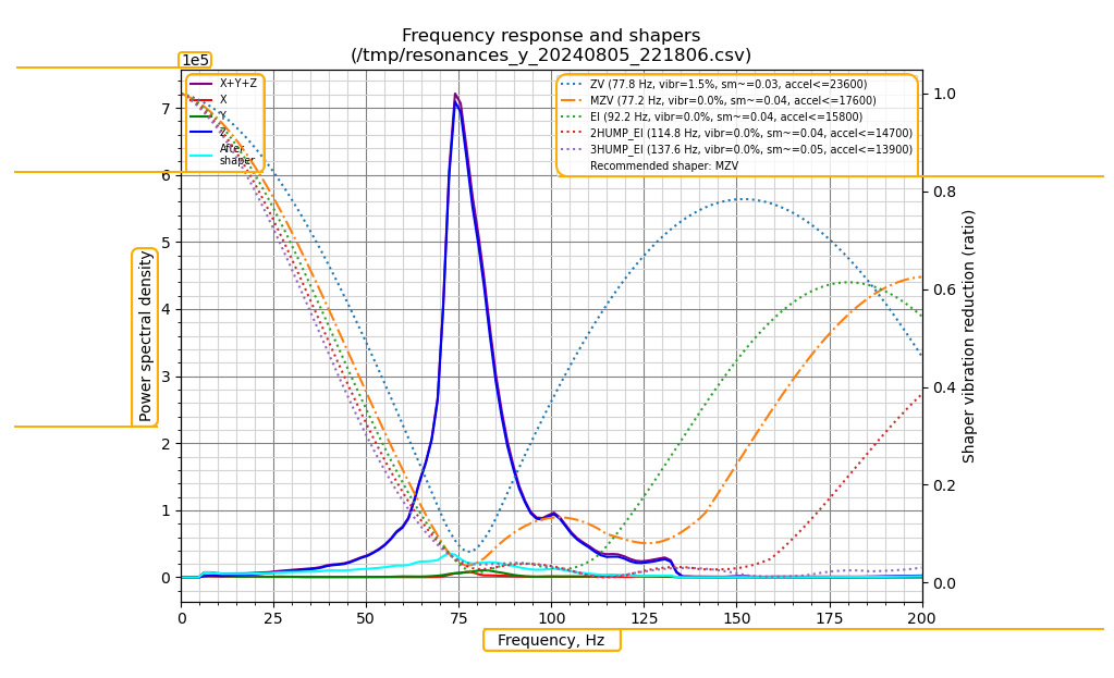
1) Power Spectral Density (PSD)
Power Spectral Density (PSD), the axis magnitude is given in scientific notation, like "1e4," meaning it has a magnitude of . Therefore, the peak value in the example has a PSD of:
If the PSD value changes to "1e5," it indicates multiplication by 100,000, adding another factor of 10.
1.1) Magnitude
"When interpreting my graphs, what value of the PSD should I pay attention to?" Assuming you are using a printer with a rigid motion system (e.g: Crossant), if you have a graph with magnitudes of and above, you likely have a noise-free and clean graph, meaning you can use that graph.
The greater the magnitude, the cleaner and better your graphs will be.
2) Accelerometer Axes
Axes config is necessary for the accelerometer to understand which axis it is detecting displacement on. You do not need to adjust this according to the movement axes of your printer, as it represents the axes of the accelerometer, not your printer.
X/Y movements: x/y movements in our graph must be equal. On this example graph, PSD of x and y is not equal, unequal axes in this graph can indicate false or harmonic resonances/noise.
Z movements: we do not expect to see z movements as any movement observed in the Z axis indicates that our toolhead is flexible/wobbly and not sufficiently rigid.
3) Shaper Details
The following list is organized from the least aggressive to the most aggressive in terms of vibration reduction and smoothing effects. The values in parentheses indicate the frequency settings for the [input_shaper] configuration.
Values in brackets
Vibr (vibration)
This represents the total remaining vibration after applying the respective shaper.
Sm (smoothing)
This term refers to smoothing, indicating how the shaper influences motion. Each shaper introduces a specific deviation from Klipper's calculated target motion, which is essential for reducing vibration. However, this deviation may also result in smoothing, leading to a loss of finer details. It provides a qualitative means to assess the effects of various shapers.
Accel (acceleration)
This denotes the maximum recommended acceleration for each shaper to prevent excessive smoothing. For instance, if a printer can handle an acceleration of 20,000, it should be capable of less acceleration when utilizing the 3HUMP_EI shaper. It's important to note that this figure is not intended to be the new acceleration setting for a printer rated at 3,000.
Lastly, the recommended shaper aims to achieve an optimal balance between smoothing and residual vibration.
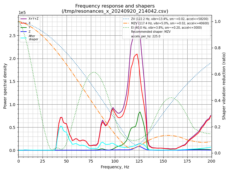
Accel Per Hz
This is one of the settings you want to adjust during testing. It's located under the [resonance_tester] and the default value is 75. When you increase this value and start a test, you will notice that your printer shakes much more aggressively. The reason for this is that this setting determines the acceleration value that will be increased per Hz.
The accel_per_hz is generally directly proportional to the PSD. A higher accel_per_hz leads to a stronger PSD. In a rigid motion system, using the default value of 75 Hz will only measure noise because the 75 Hz increment is too weak to shake the rigidity of your motion system. Therefore, when testing with a crossant, it is recommended to start from 150 and test up to 200 (or even 250 in exceptional cases).
No matter how clean your graph is, the ZV algorithm is highly aggressive and is largely not recommended for use. You might think that using ZV results in less smoothing, but due to the aggressive nature of ZV, it may not be able to cancel out any unwanted frequencies generated in your printer's motion system. As a result, you may experience defects in your prints. Our recommendation is MZV.
4) Frequency
As outlined earlier, the assessment involves a wide spectrum of frequency inputs, and the resulting frequency data is represented along the X-axis.
Smooth Input Shaper Algorithms
The Smooth Input Shaper algorithms are a collection of input shaping algorithms found in the bleeding-edge branch of Danger Klipper (current version: bleeding-edge-v2). These algorithms utilize smooth polynomial functions to minimize vibrations at specific frequencies, similar to traditional input shapers. Their aim is to provide shapers with enhanced overall performance.
Smooth shapers avaliable
- smooth_zv - Smooth version of zv input shaper
- smooth_mzv - Smooth version of mzv input shaper
- smooth_ei - Smooth version of ei input shaper
- smooth_2hump_ei - Smooth version of 2hump_ei input shaper
- smooth_zvd_ei - Zero Vibration Derivative - Extra-Insensitive Smooth Shaper (Documentation and use cases currently limited)
- smooth_si - Super Insensitive Smooth Shaper (Documentation and use cases currently limited)